Featured

PhiSch.org Personal Home Page

This is my personal home page, hosting information about some of the hobby projects that I work(ed) on in my spare time. The links in the menu will take you to the individual projects. Enjoy your stay!

Please note: The content on this site is quite old as it has been many years since I worked on the projects. Nevertheless, I have recently migrated the site to WordPress and would like to keep the content online since I’m still getting queries on some of the projects every now and then.

OpenBench Logic Sniffer Firmware Update

I had an old OpenBench Logic Sniffer (OLS) laying around that I was trying to use with PulseView. It didn’t work as nicely as I had hoped so I figured I’d try a firmware update. My device is quite old and since I bought it, the OpenBench Logic Sniffer (OLS) and its firmware are regarded as mature. This should mean: No Bugs (yeah!).

In general, I tried to follow the Guideline I found here:

http://jiggs.tk/project/open-bench-logic-sniffer-story-of-a-firmware-upgrade/

Unfortunately, this also means that the information surrounding the device can be quite dated and sometimes obsolete. So after I got it to work, I figured I’d share what I needed to do.

All of the below was done on Ubuntu 20.04.2 LTS.

Obtaining Files

The biggest challenge was obtaining the latest FPGA and PIC Firmware Binaries. Unfortunately, the links at the official OpenBench Logic Sniffer (OLS) site to the GadgetFactory-hosted Binaries are dead.

Through this link at µC.net I found a direct download link to what seemed like an official source.

Here is a direct Link to Download the File ols-0308-expert.tgz from what looks to be the official GadgetFactory GitHub Page.

For completeness, here’s the Link to the Source Code of the official OpenBench Logic Sniffer Tools.

Enter Update Mode

To put the Device in Update Mode, press the “Update” and “Reset” button at the same time. Now let go of the “Reset” button, then release the “Update” button.

The device will light both the “PWR” and the “ACT” LED near the USB Port.

FPGA Bitstream Update

The first update step is to flash the FPGA Bitstream:

$ ./ols-loader -write -erase -p:/dev/ttyACM0 -wB:./logic_sniffer_3.07-Demon-Core.bit
Logic Sniffer ROM loader v0.3 (November 9, 2010)
Opening serial port '/dev/ttyACM0' @ 921600 … OK
Found OLS HW: 1, FW: 3.0, Boot: 2
Found flash: WINBOND W25X40 
Chip erase … done :)
Reading BIN file 'logic_sniffer_3.07-Demon-Core.bit' … OK! (binary size = 169314)
Will write 662 pages 
Page 0x0000 write … (0x0000 0x0000)OK
Page 0x0001 write … (0x0000 0x0001)OK
(...)
Page 0x0293 write … (0x0002 0x0093)OK
Page 0x0294 write … (0x0002 0x0094)OK
Page 0x0295 write … (0x0002 0x0095)OK

PIC Firmware Update

Now, on to updating the PIC. First, the PIC needs to enter its Boot Loader:

$ ./ols-loader -p:/dev/ttyACM0 -t:115200 -boot
Logic Sniffer ROM loader v0.3 (November 9, 2010)
Opening serial port '/dev/ttyACM0' @ 921600 … OK
Found OLS HW: 1, FW: 3.0, Boot: 2
Found flash: WINBOND W25X40 
OLS switched to bootloader mode

The device will now show up as a Human Interface Device (HID) with USB Device ID 0xfc90 and Vendor ID 0x04d8:

$ lsusb | grep 04d8:fc90
Bus 003 Device 087: ID 04d8:fc90 Microchip Technology, Inc. 

In the dmesg Output, it can be seen like this:

$ dmesg | tail
[18973.744317] usb 3-10.1: USB disconnect, device number 86
[18973.971031] usb 3-10.1: new full-speed USB device number 87 using xhci_hcd
[18974.072878] usb 3-10.1: New USB device found, idVendor=04d8, idProduct=fc90, bcdDevice= 0.22
[18974.072880] usb 3-10.1: New USB device strings: Mfr=1, Product=2, SerialNumber=0
[18974.072882] usb 3-10.1: Product: Diolan
[18974.072884] usb 3-10.1: Manufacturer: Diolan
[18974.076704] hid-generic 0003:04D8:FC90.0010: hidraw6: USB HID v1.01 Device [Diolan Diolan] on usb-0000:00:14.0-10.1/input0

Finally, it’s time to actually flash the new PIC Firmware:

$ sudo ./ols-fw-update -e -w -m flash -vid 0x04d8 -pid 0xfc90 -ix OLSv1.firmware.v3.0.hex
U2IO flash erasing: DONE.
U2IO flash programming: DONE.
RESET Device
Operation successfully completed.

Note that the last Command needs to be run as root. Failure to do so will yield this error message:

U2IO flash erasing: FAILED.
Device is not found.
Operation aborted.
Linux VNC and Mac OS X Screen Sharing

I’ve found that in order to get x11vnc to work with the Mac OS X built-in VNC client (“Screen Sharing Application”), there options are required when starting the VNC server:

$ x11vnc -display :0 -rfbauth /home/pi/.vnc/passwd -shared -rfbversion 3.3 -forever -bg

The -shared option is key here. Judging by the log on the VNC server, I think Mac OS X will attempt multiple connections.

For what it’s worth, here’s also how to auto-start the VNC server when the user logs into the LXDE desktop. Copy and paste this to ~/.config/autostart/x11vnc.desktop:

[Desktop Entry]
Encoding=UTF-8
Type=Application
Name=VNC
Comment=
Exec=x11vnc -display :0 -rfbauth /home/pi/.vnc/passwd -shared -rfbversion 3.3 -forever -bg
StartupNotify=false
Terminal=false
Hidden=false

Working around KiCAD Printing Issues

I’m having issues printing from KiCAD, specifically Pcbnew, on Ubuntu 15.04. I’ve seen similar things on earlier versions, and also found this bug report. Even though the bug report is closed and I’m using the right wx version, the problem persists for me. So I’ve searched for a workaround.

Luckily, “plotting” from KiCAD works which makes it generate a PostScript file for each layer.

However, I need the “Edge Cuts” layer and the bottom copper layer printed on a single page. The reason is that I’m printing my layouts on transparent film, and I’m using alignment marks on the edge cuts layer to help me tape two prints on top of each other. This increases the opaqueness of my print to a point where it’s usable for me.

So here’s the steps it takes to get my PCB layout to a decent print:

  1. “Plot” the required layers from Pcbnew, leaving a bunch of PostScript files on disk.
  2. Convert the PostScript files to PDF:
    $ for ps in *.ps ; do ps2pdf $ps ; done
    
  3. Use pdftk to generate a single PDF from the relevant layers like this:
    $ pdftk layout-B_Cu.pdf background layout-Edge_Cuts.pdf output layout.pdf
    

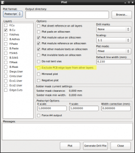
Update: There’s an option to include the “Edge Cuts” layer when plotting. Simply uncheck the “Exclude PCB edge layer from other layers” option as highlighted in the screenshot below.

Ubuntu 14.04, ThinkPad W520 and multiple Monitors

Here’s a quick reminder of the commands that I use to switch between a single monitor setup (internal laptop screen) and two external, DVI-attached monitors on my ThinkPad W520 running Ubuntu 14.04 (x86_64).

In order to switch to single-screen setup:

phs@W520:~$ disper -s -d DP-2 -r auto
phs@W520:~$ disper -s -d LVDS-1 -r auto

Switching to the two external monitors:

phs@W520:~$ disper -s -d DP-2 -r auto
phs@W520:~$ disper -e -d DP-2,DP-3 -r auto

All of this uses the stock, Ubuntu-provided driver. Didn’t have much success with the nVidia drivers (from the repositories) on this laptop.

Xilinx USB Cable on Ubuntu

Here’s what I did to install the "Xilinx Platform Cable USB II" on Ubuntu.

First, install the following two packages:

$ sudo aptitude install fxload libusb-dev

Then, download and compile the USB driver for the cable:

$ git clone git://git.zerfleddert.de/usb-driver
$ cd usb-driver
$ make
$ make lib32
$ ./setup_pcusb /opt/Xilinx/14.5/ISE_DS/ISE

If everything worked, you should see the status LED on the programmer light up after it’s plugged in.

Programming Avnet Spartan 3A FPGA Eval Board with Linux

I own a small FPGA Board by Avnet with a Spartan 3A FPGA on it. The board is nice, but unfortunately, the flash chips on the board aren’t on the JTAG chain. Instead, there is a small PSoC microcontroller that lets you programm the flashes via UART. There is a Windows tool to perform that programming which is shipped with the board. Here’s what I did to program the SPI configuration flash on Linux.

Via the FPGALibre site, I found a link to a tool called ASTriAEKiPro, which allows me to write to the FPGA SPI Configuration flash via UART and the PSoC microcontroller.

Compiling the tool is as simple as running this command:

$ make

To erase the SPI configuration flash, I used this command:

$ ./astriaekipro -p /dev/ttyACM0 -e
Avnet Spartan 3A Eval Kit Programmer v1.2.1
Copyright (c) 2009 Salvador E. Tropea 
Copyright (c) 2009 Instituto Nacional de Tecnolog�a Industrial
Embedded BPI server provided by Avnet Inc. http://www.em.avnet.com/

Erasing the memory, be patient (>1 minute) ...

To write a configuration to the SPI flash:

$ ./astriaekipro -p /dev/ttyACM0 -w 
  -b ~/sandbox/avnet_lpc/projects/13.3/avnet_lpc/avnet_i2c.bit 
Avnet Spartan 3A Eval Kit Programmer v1.2.1
Copyright (c) 2009 Salvador E. Tropea 
Copyright (c) 2009 Instituto Nacional de Tecnolog�a Industrial
Embedded BPI server provided by Avnet Inc. http://www.em.avnet.com/

Writing 235820 bytes to the serial flash, offset 0x0000000
Erasing: sector   3 (100.00 %)
Bytes written:   235820 (100.00 %)
All written!

Edit Samsung TV Channel List on Linux

Samsung TVs suck when it comes to sorting the channel list. The work-around is to transfer the channel list to a PC and edit/sort it there. To edit the channel list on Linux, I found a tool called "SamyGO ChanEdit" quite useful. Downloadable via this link.

The tool requires SWT which is installed in /usr/lib/java on my system. To start the tool, used the following command:

java -classpath .:/usr/lib/java/swt-gtk-3.8.2.jar:SamyGO-ChanEdit-v54cd.jar gui.Main