Linux VNC and Mac OS X Screen Sharing

I’ve found that in order to get x11vnc to work with the Mac OS X built-in VNC client (“Screen Sharing Application”), there options are required when starting the VNC server:

$ x11vnc -display :0 -rfbauth /home/pi/.vnc/passwd -shared -rfbversion 3.3 -forever -bg

The -shared option is key here. Judging by the log on the VNC server, I think Mac OS X will attempt multiple connections.

For what it’s worth, here’s also how to auto-start the VNC server when the user logs into the LXDE desktop. Copy and paste this to ~/.config/autostart/x11vnc.desktop:

[Desktop Entry]
Encoding=UTF-8
Type=Application
Name=VNC
Comment=
Exec=x11vnc -display :0 -rfbauth /home/pi/.vnc/passwd -shared -rfbversion 3.3 -forever -bg
StartupNotify=false
Terminal=false
Hidden=false

Working around KiCAD Printing Issues

I’m having issues printing from KiCAD, specifically Pcbnew, on Ubuntu 15.04. I’ve seen similar things on earlier versions, and also found this bug report. Even though the bug report is closed and I’m using the right wx version, the problem persists for me. So I’ve searched for a workaround.

Luckily, “plotting” from KiCAD works which makes it generate a PostScript file for each layer.

However, I need the “Edge Cuts” layer and the bottom copper layer printed on a single page. The reason is that I’m printing my layouts on transparent film, and I’m using alignment marks on the edge cuts layer to help me tape two prints on top of each other. This increases the opaqueness of my print to a point where it’s usable for me.

So here’s the steps it takes to get my PCB layout to a decent print:

  1. “Plot” the required layers from Pcbnew, leaving a bunch of PostScript files on disk.
  2. Convert the PostScript files to PDF:
    $ for ps in *.ps ; do ps2pdf $ps ; done
    
  3. Use pdftk to generate a single PDF from the relevant layers like this:
    $ pdftk layout-B_Cu.pdf background layout-Edge_Cuts.pdf output layout.pdf
    

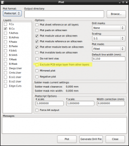
Update: There’s an option to include the “Edge Cuts” layer when plotting. Simply uncheck the “Exclude PCB edge layer from other layers” option as highlighted in the screenshot below.

Ubuntu 14.04, ThinkPad W520 and multiple Monitors

Here’s a quick reminder of the commands that I use to switch between a single monitor setup (internal laptop screen) and two external, DVI-attached monitors on my ThinkPad W520 running Ubuntu 14.04 (x86_64).

In order to switch to single-screen setup:

phs@W520:~$ disper -s -d DP-2 -r auto
phs@W520:~$ disper -s -d LVDS-1 -r auto

Switching to the two external monitors:

phs@W520:~$ disper -s -d DP-2 -r auto
phs@W520:~$ disper -e -d DP-2,DP-3 -r auto

All of this uses the stock, Ubuntu-provided driver. Didn’t have much success with the nVidia drivers (from the repositories) on this laptop.

Xilinx USB Cable on Ubuntu

Here’s what I did to install the "Xilinx Platform Cable USB II" on Ubuntu.

First, install the following two packages:

$ sudo aptitude install fxload libusb-dev

Then, download and compile the USB driver for the cable:

$ git clone git://git.zerfleddert.de/usb-driver
$ cd usb-driver
$ make
$ make lib32
$ ./setup_pcusb /opt/Xilinx/14.5/ISE_DS/ISE

If everything worked, you should see the status LED on the programmer light up after it’s plugged in.

Programming Avnet Spartan 3A FPGA Eval Board with Linux

I own a small FPGA Board by Avnet with a Spartan 3A FPGA on it. The board is nice, but unfortunately, the flash chips on the board aren’t on the JTAG chain. Instead, there is a small PSoC microcontroller that lets you programm the flashes via UART. There is a Windows tool to perform that programming which is shipped with the board. Here’s what I did to program the SPI configuration flash on Linux.

Via the FPGALibre site, I found a link to a tool called ASTriAEKiPro, which allows me to write to the FPGA SPI Configuration flash via UART and the PSoC microcontroller.

Compiling the tool is as simple as running this command:

$ make

To erase the SPI configuration flash, I used this command:

$ ./astriaekipro -p /dev/ttyACM0 -e
Avnet Spartan 3A Eval Kit Programmer v1.2.1
Copyright (c) 2009 Salvador E. Tropea 
Copyright (c) 2009 Instituto Nacional de Tecnolog�a Industrial
Embedded BPI server provided by Avnet Inc. http://www.em.avnet.com/

Erasing the memory, be patient (>1 minute) ...

To write a configuration to the SPI flash:

$ ./astriaekipro -p /dev/ttyACM0 -w 
  -b ~/sandbox/avnet_lpc/projects/13.3/avnet_lpc/avnet_i2c.bit 
Avnet Spartan 3A Eval Kit Programmer v1.2.1
Copyright (c) 2009 Salvador E. Tropea 
Copyright (c) 2009 Instituto Nacional de Tecnolog�a Industrial
Embedded BPI server provided by Avnet Inc. http://www.em.avnet.com/

Writing 235820 bytes to the serial flash, offset 0x0000000
Erasing: sector   3 (100.00 %)
Bytes written:   235820 (100.00 %)
All written!

Edit Samsung TV Channel List on Linux

Samsung TVs suck when it comes to sorting the channel list. The work-around is to transfer the channel list to a PC and edit/sort it there. To edit the channel list on Linux, I found a tool called "SamyGO ChanEdit" quite useful. Downloadable via this link.

The tool requires SWT which is installed in /usr/lib/java on my system. To start the tool, used the following command:

java -classpath .:/usr/lib/java/swt-gtk-3.8.2.jar:SamyGO-ChanEdit-v54cd.jar gui.Main

Grails, an In-Memory HSQL Database and Squirrel

Starting the HQSL Database

java -cp c:grails-1.2.0libhsqldb-1.8.0.10.jar org.hsqldb.Server -database.0 mem:devDB -dbname.0 devDB

Accessing the DB

java -cp c:grails-1.2.0libhsqldb-1.8.0.10.jar org.hsqldb.util.DatabaseManager

Grails database connection information, in DataSource.groovy

dbCreate = "create-drop"
url = "jdbc:hsqldb:hsql://localhost:9001/devDB"
username = "sa"
password = ""

Squirrel wouldn’t start until I correctly quote the CLASSPATH environment variable.

Bootable FreeBSD image on CompactFlash Card

One of the hacking toys I have is an Alix 1.C board which runs FreeBSD (9.1 at the time of writing). I started out net-booting the board but I thought it would be nice to boot the Alix board from a CompactFlash (CF) card I had laying around, too. In fact, I wanted to create a bootable image for the CF card which I could transfer to the CF card via dd(1).

Pre-requisites

Before the show could start, I needed to find out the size of the CF card I had. I did this by writing all 0s to the card.

root@T61p:~# dd if=/dev/zero of=/dev/sdb bs=512
dd: writing `/dev/sdb': No space left on device
1000945+0 records in
1000944+0 records out
512483328 bytes (512 MB) copied, 1099.51 s, 466 kB/s

I did this by inserting the card in a laptop through an PCCard adapter. The laptop on which I do my hacking runs Linux (Ubuntu 12.10 at the time of writing), so the above is the output of a Linux command. So what this revealed is that the card has 1,000,944 blocks of 512 Bytes which is a total capacity of 512,483,328 Bytes or 488.74 MBytes.

Setting up the Partition Table

Now that we know the size of the CF card, we can create the bootable image. The first step is to create a file of exactly the size as the CF card. This can be done simply by running a command like this:

[phs@freebsd ~]$ dd if=/dev/zero of=freebsd-alix.img bs=512 count=1000944
1000944+0 records in
1000944+0 records out
512483328 bytes transferred in 18.620906 secs (27521933 bytes/sec)

Next, we need a virtual disk based on that image to work with. The solution is to create memory disk as described in the FreeBSD handbook’s section 19.13 on virtual disks. As root, do this:

freebsd# mdconfig -a -t vnode -f /home/phs/freebsd-alix.img -u 0

This creates /dev/md0. Of course, nothing’s on that disk, yet. The first thing to do is creating a partition table.

freebsd# gpart create -s gpt md0
md0 created

This creates an empty UEFI-compatible GPT partition table, but no partitions, yet. You can examine the partition table like this:

freebsd# gpart show
(...)
=>     34  1000877  md0  GPT  (488M)
       34  1000877       - free -  (488M)

In order to boot FreeBSD from the image later, at least two partitions are required: A partition of 512K containing the boot code, and one partition containing the actual operating system. Because I wrote an I2C device driver for the Alix 1.C, I also want a swap partition so I have some space for kernel dumps.

freebsd# gpart add -t freebsd-boot -l boot -s 512K md0
md0p1 added
freebsd# gpart add -t freebsd-swap -l swap -s 64M md0
md0p2 added

Before adding the third partition for the FreeBSD operating system, find out how much space is left on the device by examining the partition table:

freebsd# gpart show md0
=>     34  1000877  md0  GPT  (488M)
       34     1024    1  freebsd-boot  (512k)
     1058   131072    2  freebsd-swap  (64M)
   132130   868781       - free -  (424M)

Ok, now create the data partition:

freebsd# gpart add -t freebsd-ufs -l rootfs -s 868781 md0
md0p3 added

Embedding the boot code

Now that the partition structure is laid out, it’s time to make the image bootable. FreeBSD’s gpart(8) manual page offers great information on what those files are and do: pmbr is a "protective MBF" which allows legacy, BIOS-based systems to boot the image. The MBR code searches the GPT for a freebsd-boot partition and starts the secondary boot code from there. In this case, that’s gptboot which searches the GPT for a freebsd-ufs partition from which it loads /boot/loader.

The following command writes the boot code to the image. Note that I’m using the files from /usr/obj, i.e. the ones most recently build from source and not the one’s currently installed.

freebsd# gpart bootcode -b /usr/obj/usr/src/sys/boot/i386/pmbr/pmbr
  -p /usr/obj/usr/src/sys/boot/i386/gptboot/gptboot -i 1 md0
bootcode written to md0

Initializing the root file system partition

The third partition which is supposed to store the operating system must be initialized with a file system before it can be written.

freebsd# newfs -L FreeBSD -U /dev/gpt/rootfs 
/dev/gpt/rootfs: 424.2MB (868776 sectors) block size 32768, fragment size 4096
        using 4 cylinder groups of 106.06MB, 3394 blks, 13696 inodes.
        with soft updates
super-block backups (for fsck_ffs -b #) at:
 192, 217408, 434624, 651840

This creates an empty UFS2-based file system with soft-updates enabled on the partition which can be mounted:

freebsd# mount /dev/md0p3 /mnt
freebsd# df -h
Filesystem     Size    Used   Avail Capacity  Mounted on
(...)
/dev/md0p3     410M    8.0k    377M     0%    /mnt

Installing FreeBSD to the bootable image

Installing the operating system is as easy as this:

[phs@freebsd /usr/src]$ sudo make installkernel KERNCONF=ALIX1C DESTDIR=/mnt
--------------------------------------------------------------
>>> Installing kernel ALIX1C
--------------------------------------------------------------
(...)
[phs@freebsd /usr/src]$ sudo make installworld DESTDIR=/mnt
(...)
[phs@freebsd /usr/src]$ sudo make DESTDIR=/mnt distrib-dirs distribution
(...)

Before the image is really useful, you probably want to adjust a few config files here and there. Especially etc/fstab should be configured so that the root file system is found and mounted when booting:

[phs@freebsd /mnt]$ cat etc/fstab 
# Device        Mountpoint  FSType  Options Dump    Pass
/dev/ada0p3     /           ufs     ro      0       0
/dev/ada0p2     none        swap    sw      0       0

In my case, the Alix 1.C board has a serial console but no screen. In order to get a login prompt on the serial console, etc/ttys needs to contain a line like this one:

ttyu0   "/usr/libexec/getty std.115200" vt100   on  secure

Finally, a root password must be set:

# pw -V /mnt/etc usermod root -h 0

When done, transfer the image to the CF card using dd(1).

Update Jan 24th, 2013: There are a few more files than just /etc/fstab that should be adjusted – added a few words about those.
Booting a PowerBook from a LiveCD image on an USB-Stick

I have an old Apple PowerBook G4 with a broken CD/DVD drive. For most practical purposes, the broken drive is no issue. However, if you’re going to re-install the laptop, it becomes one. Luckily, the PowerBook is able to boot from USB…

At first, I tried following the instructions on "LiveUSB on PPC" found in Gentoo’s Wiki, but that didn’t work out at first. I then found a blog entry titled "Creating a bootable USB Stick with Mac OS X in 10 easy steps&quot. Combining the two lead to success, so here’s what I did:

  • I downloaded the latest PowerPC release of Finnix, a &quot self-contained, bootable Linux CD distribution&quot from the project’s front page.

  • I re-named the ISO image from finnix-ppc-105.iso to finnix-ppc-105.dmg. Also, I displayed the file’s information in Finder by right-clicking on the file icon and selecting "Show Information&quot. I doubt that this step is required but it certainly didn’t do any harm.

  • From a shell, aka "Terminal Window&quot, I used the command diskutil list to find the device path to my USB drive. In my case, it was /dev/disk6.

  • I then unmounted the drive by running

    $ diskutil unmountDisk /dev/disk6

  • Using good, old dd(1), I wrote the disk image to the USB drive:

    $ sudo dd if=finnix-ppc-105.dmg of=/dev/disk6 bs=1m
  • Finnally, I unmounted the drive by running:

    $ diskutil eject /dev/disk6

In order to boot the PowerBook from the USB drive, I had to drop into Open Firmware. In case you didn’t know it, this is done by holding down Cmd+Option+o+f right after the computer is turned on.

The next step was to find the device node of the bootable USB drive. To do this, I browsed the device tree for any USB node that had a disk child node.

> dev /
> ls

In my case, the USB drive was at /pci@f2000000/usb@1b,1/disk@1.

The instruction found on the Gentoo wiki assign the cd alias to that node, so I did that, too, by running:

> devalias cd /pci@f2000000/usb@1b,1/disk@1

This allowed me to finally boot from the USB drive like this:

> boot cd:,\:tbxi

Ubuntu 11.10 on Lenovo W520

At work, I got a new laptop — a Lenovo W520. It came with Ubuntu 11.10 ("Oneiric Ocelot") pre-installed by the support team. My first impression was that it worked pretty well, but I quickly discovered that I couldn’t change the brightness of the display through the Fn+Home/End keys.

The W520 uses this “Optimus” technology with an integrated on-board graphics card plus a separate NVIDIA card, where both cards can be switched on-the-fly — on Windows. The default installation used the high performance card and I suspected that the video card driver was keeping me from adjusting the brightness. As it turns out, after switching to the on-board Intel card, things worked fine. Here’s what I needed to do:

First, I needed to disable the NVIDIA card in “the BIOS” and switch to the on-board card. There’s an option somewhere under “Setup”, then “Display”, if I recall correctly.

Next, I changed the video card section in my /etc/X11/xorg.conf to read this:

Section "Device"
  Identifier "Device0"
  Driver "intel"
  Option "Shadow" "True"
  Option "DRI" "True"
EndSection

In fact, I added the two Option lines later on and only changed the Driver line at first. I then discovered that most of the little try icons in the upper right corner of the Gnome desktop wouldn’t show anymore. A look at /var/log/Xorg.0.log turned up some errors and running glxinfo yielded lines like these:

Xlib:  extension "GLX" missing on display ":0.0".

Luckily, someone else ran into the same issues over at http://theiszm.wordpress.com/2010/06/27/glx-missing-on-display/. As indicated there, I also ran these commands:

$ sudo apt-get purge nvidia*
$ sudo apt-get install --reinstall xserver-xorg-video-intel 
    libgl1-mesa-glx libgl1-mesa-dri xserver-xorg-core
$ sudo dpkg-reconfigure xserver-xorg
$ sudo update-alternatives --remove gl_conf /usr/lib/nvidia-current/ld.so.conf

The first command hinted that some "ubuntu-desktop" package would also be removed. I don’t know what that is, but I don’t miss it, yet. Anyways, after a final reboot, the brightness adjustment now works and all my tray icons are back in place.